-SIMULATION-AND-IMPLEMENTATION-OF-VARIOUS-SPWM-TECHNIQUES-OF-MULTILEVEL-INVERTER-
ABSTRACT
Large electric drives & utility applications necessitates modern power electronics converter like cascaded H-bridge multilevel inverter (CHB) with separated DC source. CHB is most practical for use as a power converter for medium & high power applications. The H-bridge inverter removes large no. of bulky transformers, clamping diodes & flying capacitors. Cascaded multilevel inverter (MLI) aims for medium & high power applications. There are many PWM techniques used for controlling MLI among these, SPWM is well-known for its simplicity in both hardware & software. But SVM becomes complex when level increases. In this project, SPWM controlled cascaded H-bridge MLI is designed , analyzed & compared with conventional inverter by simulating in MATLAB simulink software.
OBJECTIVE
The objective of this project is to compare the different modulation technique used for controlling the cascaded H-bridge multilevel inverter. These comparison is done with respect to analyse the switching pattern & THD for different modulation techniques. For these comparisons all of the inverters are simulated in MATLAB/SIMULINK.
NECESSITY
The elementary concept of a multilevel converter to achieve higher power is to use a series of power semiconductor switches with several lower voltage dc sources to perform the power conversion by synthesizing a staircase voltage waveform. Capacitors, batteries, and renewable energy voltage sources can be used as the multiple dc voltage sources. The commutation of the power switches aggregate these multiple dc sources in order to achieve high voltage at the output; however, the rated voltage of the power semiconductor switches depends only upon the rating of the dc voltage sources to which they are connected. A multilevel converter has several advantages over a conventional two-level converter that uses high switching frequency pulse width modulation (PWM). The attractive features of a multilevel converter can be briefly summarized as follows.
- Staircase waveform quality: Multilevel converters not only can generate the output voltages with very low distortion, but also can reduce the dv/dt stresses; therefore electromagnetic compatibility (EMC) problems can be reduced.
- Common-mode (CM) voltage: Multilevel converters produce smaller CM voltage; therefore, the stress in the bearings of a motor connected to a multilevel motor drive can be reduced. Furthermore, CM voltage can be eliminated by using advanced modulation strategies such as that proposed in .
- Input current: Multilevel converters can draw input current with low distortion.
- Switching frequency: Multilevel converters can operate at both fundamental switching frequency and high switching frequency PWM. It should be noted that lower switching frequency usually means lower switching loss and higher efficiency. Multilevel converters do have some disadvantages. One particular disadvantage is the greater number of power semiconductor switches needed. Although lower voltage rated switches can be utilized in a multilevel converter, each switch requires a related gate drive circuit. This may cause the overall system to be more expensive and complex.
OUTCOME
The outcome of this project is to compare the SPWM’s two technique & to analyse the output voltage waveforms & THD. Also to find the best modulation technique among these two main PWM techniques.
### INTRODUCTION :Cascaded Multilevel Inverter

FIG1 :- Three phase five level CHB MLI
CONTROL TECHNIQUES OF MULTILEVEL INVERTER(MLI)

FIG2 :- Classification of various control techniques of H-bridge MLI
MATLAB SIMULATION & RESULT
1. CIRCUIT DIAGRAM OF 1-PHASE 5-LEVEL INVERTER

FIG3 :- Circuit Diagram Of 5-Level Inverter Controlled By Phase Shifted SPWM Technique
RESULTS
GATE PULSES

FIG4 :- Waveform of Gating Signal To Various Switches Of 5-Level Inverter Controlled By Phase Shift Technique
OUTPUT VOLTAGE

FIG5:-Output waveform of 1-Phase 5-Level Inverter Controlled By SPWM Phase shifted technique, Mf=20,Ma=0.8
FFT ANALYSIS

FIG6 :-FFT analysis Of 5-Level Inverter Controlled By SPWM Phase shift technique**THD=38.34%
### 2. 3-PHASE 5-LEVEL INVERTER CONTROLLED BY SPWM PHASE SHIFTED TECHNIQUE

FIG7:- Circuit Diagram Of 3-Phase 5-Level Inverter Controlled By SPWM Phase Shifted Technique
### RESULTS #### VOLTAGE WAVEFORMS ##### PHASE VOLTAGES

FIG8 :- Line To Ground Voltage
##### LINE VOLTAGE VOLTAGES

FIG9 :- Line To Line Voltage
### FFT ANALYSIS #### FFT ANALYSIS OF PHASE VOLTAGE

FIG10:- FFT analysis of 3-Phase Phase voltage**THD=40.83
#### FFT ANALYSIS OF LINE VOLTAGE

FIG11:- FFT analysis of 3-Phase Line voltage **THD=31.75%**
### LEVEL SHIFTED SPWM TECHNIQUE
#### IN PHASE DISPOSITION TECHNIQUE(IPD)
##### CIRCUIT DIAGRAM OF 1-PHASE 5-LEVEL INVETER CONTROLLED BY IPD

FIG12:- Circuit Diagram Of 1-Phase 5-Level Inverter Controlled By IPD
RESULTS
GATING SIGNALS

FIG13:-Waveform of Gating Signal To Various Switches Of 5-Level Inverter Controlled By IPD Level Shift Technique
OUTPUT VOLTAGE

FIG14:- Output waveform of 1-Phase 5-Level Inverter Controlled By IPD Level shifted technique ,Mf =20, Ma =0.8
FFT ANALYSIS
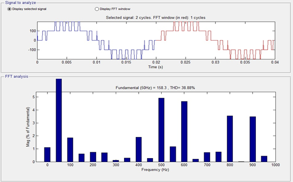
FIG15:-FFT analysis of Output Voltage of 1-Phase MLI using IPD**THD=38.88%**
3-PHASE 5-LEVEL INVETER CONTROLLED BY IPD

FIG16 :- Circuit Diagram Of 3-Phase 5-Level Inverter Controlled BY IPD
RESULTS
#### OUTPUT VOLTAGE
##### PHASE VOLTAGE

FIG17:- Waveform of Phase Voltage of 3-Phase MLI using IPD
LINE VOLTAGE

FIG18:- Waveform of Line Voltage of 3-Phase MLI using IPD
FFT ANALYSIS
FFT ANALYSIS OF PHASE VOLTAGE

FIG19:- FFT analysis of 3-Phase Line to Ground voltage **THD=38.88%**
FFT ANALYSIS OF LINE VOLTAGE

FIG20:- FFT analysis of 3-Phase Line voltage **THD=21.34%**
PHASE OPPOSITE DISPOSITION TECHNIQUE(POD)
CIRCUIT DIAGRAM OF 1-PHASE 5-LEVEL INVETER CONTROLLED BY POD TECHNIQUE

FIG21 :-Circuit Diagram Of 3-Phase 5-Level Inverter Controlled By SPWM POD Level Shifted Technique
RESULTS
GATING SIGNALS

FIG22:- Waveform of Gating Signal To Various Switches Of 5-Level Inverter Controlled By POD Level Shift Technique
OUTPUT VOLTAGE

FIG23:- Output waveform of 1-Phase 5-Level Inverter Controlled By POD Level shifted technique ,Mf=20,Ma=0.8
FFT ANALYSIS

FIG24:- FFT analysis of Output Voltage of 1-Phase MLI using POD**THD=38.57%*
CIRCUIT DIAGRAM OF 3-PHASE 5-LEVEL INVETER CONTROLLED BY POD TECHNIQUE

FIG25:- CIRCUIT DIAGRAM OF 3-PHASE 5-LEVEL INVETER CONTROLLED BY POD
RESULTS
OUTPUT VOLTAGE
PHASE VOLTAGE

FIG26:-Waveform of Line Voltage of 3-Phase Line To Ground Voltage MLI using POD
LINE VOLTAGE

FIG27- Waveform of Line Voltage of 3-Phase MLI using POD
FFT ANALYSIS
FFT ANALYSIS OF PHASE VOLTAGE

FIG28:- FFT analysis of 3-Phase Line To Ground voltage using POD **THD=38.57%**
FFT ANALYSIS OF LINE VOLTAGE

FIG29:- FFT analysis of 3-Phase Line voltage using POD **THD=35.37%**
ALTERNATE PHASE OPPOSITE DISPOSITION TECHNIQUE(APOD):-
CIRCUIT DIAGRAM OF 1-PHASE 5-LEVEL INVETER CONTROLLED BY APOD

FIG30:- Circuit Diagram Of 1-Phase 5-Level Inverter Controlled By SPWM APOD Level Shifted Technique
RESULTS
GATING SIGNALS

FIG31:-Waveform of Gating Signal To Various Switches Of 5-Level Inverter Controlled By APOD Level Shift Technique
OUTPUT VOLTAGE

FIG32:- Output waveform of 1-Phase 5-Level Inverter Controlled By SPWM APOD Level Shifted Technique ,Mf =20, Ma =0.8
FFT ANALYSIS

FIG33:- FFT analysis of Output Voltage of 1-Phase MLI using APOD**THD=39.10%**
3-PHASE 5-LEVEL INVETER CONTROLLED BY APOD

FIG34:- CIRCUIT DIAGRAM OF 3-PHASE 5-LEVEL INVETER CONTROLLED BY APOD
#### RESULTS
OUTPUT VOLTAGE
PHASE VOLTAGE

FIG35:- Waveform of Voltage of 3-Phase Line To Ground Voltage MLI using APOD
LINE VOLTAGE

FIG36:-Waveform of Line Voltage of 3-Phase MLI using APOD
FFT ANALYSIS
FFT ANALYSIS OF PHASE VOLTAGE

FIG37:-FFT analysis of 3-Phase Line To Ground voltage using APOD **THD=39.10%**
FFT ANALYSIS OF LINE VOLTAGE

FIG38:- FFT analysis of 3-Phase Line voltage using APOD **THD=29.79%**
SIMULATION RESULTS AT GLANCE:-

HARDWARE

FIG39:-CIRCUIT DIAGRAM
Hardware implementation

CONCLUSION
The cascaded multilevel inverters have evolved from a theoretical concept to real applications due to several remarkable features like a high degree of modularity, the possibility of connecting directly to medium voltage, low harmonic distortion, and the control of power flow in the regenerative version. The focus of this project is limited to basic concept of different MLI and comparative study of different PWM generation methods and its impact on inverter output.
REFERENCE
[1]A. Kale, A. Tamhane and A. Kalage, “Comparative study of SPWM And SVPWM cascaded h-bridge multilevel inverter”, 2017 International Conference on Intelligent Computing and Control (I2C2), 2017
[2]N. Salgado-Herrera, A. Medina-Rios, A. Ramos-Paz and J. Rodriguez-Rodriguez, “Generation of a multilevel SPWM technique of 3, 9 and 21 levels with FPGAs”, 2013 North American Power Symposium (NAPS), 2013.
[3] Mustafa S. Alkhazragi, Nabil K.AL-Shamaa “Cascaded H-Bridge Multilevel Inverter Using SPWM and MSPWM Strategies”, Int. Journal of Engineering Research and Application ISSN : 2248-9622, Vol. 7, Issue 6, (Part -2) June 2017, pp.14-20
[4] Vinayaka B.C, S. Nagendra Prasad, “Modeling and Design of Five Level Cascaded H-Bridge Multilevel Inverter with DC/DC Boost Converter”,Int. Journal of Engineering Research and Applications ISSN : 2248-9622, Vol. 4, Issue 6( Version 5), June 2014, pp.50-55
[5]B. Kumar and M. Lokhande, “An enhanced space vector PWM for nine-level inverter employing single voltage source”, 2017 IEEE Transportation Electrification Conference (ITEC-India), 2017.
[6] P. Bhagwat and V. Stefanovic, “Generalized Structure of a Multilevel PWM Inverter”, IEEE Transactions on Industry Applications, vol. -19, no. 6, pp. 1057-1069, 1983.